It's raining, It's pouring

For Pcomp this week I used an analog raindrop sensor board to simulate rainfall in p5. The sensor "senses rain" when water shorts the connections running throughout the board. I adapted some code Daniel Shiffman wrote for a purple rain sketch to create the rain effect when p5 reads the sensor value in via serial. This was my first time using p5 and I found it super easy to use, if not a little basic (seems a lot easier to get started with than something like d3).


The circuit itself was super straightforward, nano + sensor:

Fritzing diagrams:


Arduino code:

#define RAIN_SENSOR_PIN A7

void setup() {
  Serial.begin(9600);
  while (!Serial) {
  }
}

void loop() {
  int rainValue = analogRead(RAIN_SENSOR_PIN);
  rainValue = map(rainValue, 0, 1023, 50, -16); //map sensor on 0-50 scale
  Serial.println(rainValue);
  delay(1);
}

Sketch.js code:


// Code adapted from Daniel Shiffman's purple rain coding challenge
// https://youtu.be/KkyIDI6rQJI

// define global vars
var drops = [];
var serial;
var portName = '/dev/cu.wchusbserial1410';
var sensorData = 0;
var rainData = 0;
var rainSound;

function preload(){
  rainSound = loadSound("rain.mp3");
}

function setup() {
  createCanvas(640, 360);
  for (var i = 0; i < 1000; i++) {
    drops[i] = new Drop();
  }

  rainSound.play();

  serial = new p5.SerialPort();
	serial.on('connected', serverConnected);
	serial.on('open', portOpen);
	serial.on('data', serialEvent);

	serial.list();
	serial.open(portName);
}

function serverConnected() {
  //println('connected to server.');
}

function portOpen() {
  //println('the serial port opened.')
}

function serialEvent() {
	sensorData = serial.readLine();
}

function draw() {
  background(220,220,220);

  rainData = lerp(rainData, sensorData, 0.04);
  text("rain percentage: " + round((rainData /50)*100) + "%", 30, 30);

  var rainAmount = rainData * 15; 
  for (var i = 0; i < rainAmount; i++) {
    drops[i].fall();
    drops[i].show();
  }

  var rainVol = rainData * 2
  var volume = map(rainVol, 0, 50, 0, 1);
  rainSound.setVolume(volume);
}

Leather Pouch/Chalk Bag

Over Columbus Day weekend I stayed in a cabin up in the Adirondacks with my dad. One morning when we went into Saranac Lake there was a small farmers market going on. One of the vendors was a guy selling rustic furniture--Adirondack chairs, tables, etc. I talked with him for a bit about the materials he was using, and he offered to sell me all the leather scraps he had on him for $10. I forgot to take a photo of this while it was happening, but I did get one later of my dog sleeping behind the pile I took home:

I waited a little too long to start on this project, and getting the leather turned out to be the easiest part. I went to Lowes, Blick, and Michael's for tools, and all 3 were sold out of leather punches. Michael's was the only store that carried eyelet grommets in a smaller size, but they were out of the correct size attachment tool. REI Soho was out of both 5mm and 6mm accessory cord. Lesson learned: get it together in advance.

My initial plan was to make a leather chalk bag. I didn't really have enough material to make a full size one, so it ended up being more of a pouch, but it could still be functionally used as a chalk bag.

I first tested a cut on the 75 watt laser using the recommended 30% speed/100% power, and had to make 3 passes to cut through:

My template for the pouch in Ai had 8 holes for eyelets (which turned out to be way too few to cinch the whole thing together):

I used the same settings to cut it out, which worked, but smelled pretty bad:

Next, I added the eyehole grommets. Since I couldn't get the correct size punch tool, I resorted to doing this by hand using pliers and a hammer. I hated the stain/dye color on the smooth side, so I chose to use the rough out side as the outside:

All the grommets pushed through and flattened on the inside:

I knew that I wanted to line the pouch with another material, and I planned to use the sewing machines in the soft lab to do that. After talking to some 2nd years (shoutout to Lindsey!), it became apparent that we did not have the necessary equipment to go through 2 layers of leather and 1 layer of polyester. I resorted to sewing everything together by hand. I used some black polyester scrap material and tested it out on a leather scrap piece:

Hand sewing is hard...the inside (above) looks worse, but the outside was still fairly rough:

The good news is that the stitching wouldn't be very visible once the pouch was finished and cinched together. I took apart a piece of 5mm cord that I was using as a prusik loop for climbing and used it as the cord for the pouch:

Unfortunately, the wide spacing of the eyelets resulted in the pouch not really cinching together as a pouch--more like a lump with a cord through it. I had to pivot a bit and sew the cord directly into the leather and remove all but 2 eyelets. Here it is almost finished (looks kind of like an apple tart crust to me):

Finished stitching:

Cinching it all together after stitching it:

It's not my favorite thing I ever made, but I'm pretty proud of it considering I have never worked with leather before and I haven't stitched anything in over 10 years. It kind of looks like a video game coin purse (Zelda?), which I love.

Pi Music Box

I've been toying with the idea of using a Pi Zero to build a wireless music streaming box for a while. My original plan was to use cherry wood and metal to give the box a Hi-Fi look, but the wood I ordered from Rockler ended up getting delayed, and isn't coming until this Friday (10/6).

While looking at different boxes at the container store I came across a hockey puck display case made of acrylic that fit my parts and would provide an opportunity to etch the top. From a design perspective, I liked the idea of sticking a single metal knob onto the front of the box to control the volume and having the rest of the box remain clear to show off the "guts".

I definitely bit off more than I could chew for a 1 week project. I continued to add complexity (why not add a powered amp on Tuesday!), despite not having a ton of time.  I spent around 20 hours on this project, 3/4 of that was the "comp" side--both hardware (lots of wiring + soldering) and software (I now hate ALSA in linux). Ultimately, if I had scaled down the complexity this would've been more successful. That said, I'm fairly happy with the results as a starting point for a longer project.

Materials Used

  • Raspberry Pi Zero W
  • Pimoroni Phat DAC
  • Acrylic hockey puck case
  • Surface mount parts (10k pot, DC jack, 1/8" stereo jack)
  • Analog to digital converter (MCP3008)
  • 5v voltage regulator
  • Adafruit 20W class D amp
  • Perf board + wiring and solder

On the electronics side, I started with a lot of components I already had on hand:

The Pi doesn't have any analog inputs on the GPIO header, so I had to use an analog to digital chip into my circuit in order to control the volume with a potentiometer. The volume control happens at the software level via a Python script I cobbled together from an Adafruit library:

Poorly soldered (but working) header pins:

I put it all together on a perf board:

Since I had previously soldered pins into the DAC I had to cut some out with clippers to make the A2D chip pins fit:

It works:

[video width="272" height="480" m4v="http://blog.nickwallace.us/wp-content/uploads/sites/2/2017/10/IMG_0088.m4v"][/video]

With the basic hardware setup, I started on the box by drilling a hole for the pot in the center of the case:

Pot mounted:

The next day, I was digging through stuff at home and came across a 20w amp I bought from Adafruit a while ago. "Why not make this project more complicated, even though you have no time to work on it?" I thought. I then spend 2-3 hours pulling off surface mount parts, attaching panel mount parts, and wiring the output to a 5v regulator circuit to power the Pi + DAC:

Wired up with sweet metal knob attached:

In my haste to drill a spot for the DC jack, I cracked the case. Fortunately, the corner remained intact, so I was able to continue for the time being:

I drilled the hole for the audio jack freehand using a dremel:

Aaaand my surface mount audio jack doesn't fit:

Testing the fit. Unfortunately, the way I wired the 12 -> 5v regulator to the perf board really screwd things up, making for a sloppy fit. If I had taken more time to plan it out I could've avoided this:

I laser etched a Pi logo onto the top of the case @ 90%/40%:

Not particularly happy with the "final" product, but it's a start. I bought another hockey puck case and am going to redo this minus the amp + voltage regulator and clean up the wiring. I will probably also add some small spacers between the bottom of the box and the Pi and perf board to give it a cleaner look.


Adventures with Arduino, PWM, Servos, and Tones

[video width="272" height="480" m4v="http://www.nickwallace.us/blog/wp-content/uploads/2017/10/IMG_0102.m4v"][/video] While reviewing Pcomp concepts this week, I tried mocking up a small scale version of an automated dog feeder that I want to build in the future. I built a cardboard prototype dog feeder that plays a noise and rotates a servo when a button is pressed--the servo is attached to a wheel which dumps the food into a ramp that outputs out of the box it is inside.

This is the initial design sketchup:

Besides learning more about servos and how to create sounds with an Arduino, this was a good lesson in prototyping--my design changed 3-4 times, and I now have a better idea of the tolerances I will need to build into my final design. I also used fritzing for the first time to build a circuit diagram, to decent success.

I build the box and wheel out of cardboard that I laser cut:

Breadboarding the servo setup (fritzing diagram at the bottom):

Testing the servo action:

[video width="272" height="480" m4v="http://www.nickwallace.us/blog/wp-content/uploads/2017/10/IMG_0073.m4v"][/video]

I mounted the servo to the back of the cardboard box, and glued the wheel to the servo horns. Testing:

[video width="272" height="480" m4v="http://www.nickwallace.us/blog/wp-content/uploads/2017/10/IMG_0074.m4v"][/video]

I built out more of the box, and realized I would need some additional "stopped" guards on the inside of the ramps to prevent spillage:

Attempted fritzing diagram:


Arduino code:

// Add libraries
#include <Servo.h>
#include <time.h>
#include <TimeAlarms.h>
#include <pitches.h>

// Setup manual feed button
#define MANUAL_FEED_PIN 3
#define SPEAKER_PIN 8
boolean manual;
int buttonState = 0;         // current state of the button
int lastButtonState = 0;     // previous state of the button

// Setup Servo
Servo dogFeeder;
int potPin = 0; // Pin used to control potentiometer for servo
int potVal; // Value of potentiometer

// tone/music code taken from tone sketch by Tom Igoe
// zelda "secret unlock" melody (ish) created by ear
int melody[] = {
  NOTE_G4, NOTE_FS4, NOTE_DS5, NOTE_A4, NOTE_GS3, NOTE_E5, NOTE_GS5, NOTE_C6
};

// note durations: 4 = quarter note, 8 = eighth note, etc.:
int noteDurations[] = {
  8, 8, 8, 8, 8, 8, 8, 8
};

void setup() {
  Serial.begin(9600);
  Serial.println("Doggo-matic Online!");
  Serial.println("------------------------------------------------");
  Serial.println();

  dogFeeder.attach(2); // Servo on pin 2

  // Setup alarms
  Alarm.alarmRepeat(9, 00, 0, feed); // Morning feed: 9am
  Alarm.alarmRepeat(19, 00, 0, feed); // Evening feed: 7pm
}

void loop() {
  buttonState = digitalRead(MANUAL_FEED_PIN); // Read the manual feed button input pin

  // Check if button has been pressed by comparing to previous state
  if (buttonState != lastButtonState) {

    // If the state has changed, feed the dog
    if (buttonState == HIGH) {
      manual = true;

      for (int thisNote = 0; thisNote < 8; thisNote++) {
        // to calculate the note duration, take one second
        // divided by the note type.
        //e.g. quarter note = 1000 / 4, eighth note = 1000/8, etc.
        int noteDuration = 1000 / noteDurations[thisNote];
        tone(8, melody[thisNote], noteDuration);

        // to distinguish the notes, set a minimum time between them.
        // the note's duration + 30% seems to work well:
        int pauseBetweenNotes = noteDuration * 1.30;
        delay(pauseBetweenNotes);
        // stop the tone playing:
        noTone(8);
      }

      feed();
    }

    // Delay a little bit to avoid bouncing
    delay(50);
  }

  // Save the current state as the last state, for next time through the loop
  lastButtonState = buttonState;

}

void feed() {

  // Play food sound
  // CODE HERE

  // Read in pot value and turn servo accordingly
  potVal = analogRead(potPin);
  potVal = map(potVal, 0, 1023, 500, 2000); // Map value to 0.5-2 sec delay

  dogFeeder.write(170); // Move the servo to dispense food
  delay(potVal);
  dogFeeder.write(0); // Reset the servo

  time_t lastFed = now();

  // Play sit command sound
  // CODE HERE

  if (manual == true) {
    Serial.println("Doggo fed at: [TIME GOES HERE]! (manual)");
    Serial.println();
    manual = false;
  } else {
    Serial.println("Doggo fed at: [TIME GOES HERE]!");
    Serial.println();
  }
}

Rapid Prototyping with Cardboard

Before coming to ITP, I had never used Adobe Illustrator (Ai) or a laser cutter. I'm very happy that has changed.

I was previously working on an automated dog feeder project, but had been struggling with material handling. My original design involved a single ramp inside a box, angled toward an opening in the bottom that was blocked by a piece moved by a servo. Unfortunately, the dog food would continuously jam in the opening with this method.

I redesigned the whole thing for version 2.

The new design funnels the dog food to a single point and dumps it into a "wheel" with cross sections that catch the food. The cross section wheel is moved by a servo, which dumps the controlled amount into a final chute and comes out into the dog's bowl from there:

I grabbed a spare cardboard box and cut it into long pieces with a box cutter:

Building out a template file in Ai:

It's alive! I used 30% speed and 90% power to start with, had to make 2 passes:

[video width="640" height="360" m4v="http://www.nickwallace.us/blog/wp-content/uploads/2017/09/IMG_0062.m4v"][/video]

My first cut on a laser cutter:

Putting the pieces together:

Hard to tell from the photo, but they're a little lose after the first try:

I reduced the gap down to .15" and played with a variety of sizes for the circle and height of the X:

I settled on a 7" circle with 3" high sides:

Setting up my breadboard + arduino + servo:

Cam Switches

[video width="272" height="480" m4v="http://www.nickwallace.us/blog/wp-content/uploads/2017/09/IMG_0030.m4v"][/video] I decided to combine my Pcomp and Intro to Fab projects for this week.

I knew that I wanted to build something for ItF that would require me to make compound cuts on the miter saw (something I've never done before), but wasn't quite sure how to integrate that into a switch. I was reorganizing some climbing gear on Sunday when I suddenly had the idea to build a switch that would be connected by the lobes of a cam.


I drew up a design for an open frame with metal on the inside. When you insert a cam into the frame, the circuit is completed--lighting up an LED on the top of the frame:

I initially tried ripping a 2x4 on the bandsaw, which didn't work out well:

I ended up switching to some scrap 1" plywood I found and cutting 3" sections on the panel saw:

From there, I setup the miter saw to cut at a 45 degree angle and created a backstop to cut the sides:

Final miter saw cuts:

Pretty rough around the edges, I did a quick pass on the belt sander to smooth most out:

Next, I used the drill press to make holes for the LEDs on top:

All drilled:

I mounted the LEDs into the holes, bent the cathode to one side, and soldered a longer lead to the annode:

I then glued up the bottom 3/4 of the frames:

I used an extra side piece to form and cut the foil:

2 pieces of foil were placed on the inner sides of the frames before I glued the tops on:

At this point, I tested them using a AA battery holder:

[video width="272" height="480" m4v="http://www.nickwallace.us/blog/wp-content/uploads/2017/09/IMG_0030.m4v"][/video]

I then glued the positive wires to the frames:


Added batteries in series, hot glued + taped:

It works, but the connection sucks:

[video width="272" height="480" m4v="http://www.nickwallace.us/blog/wp-content/uploads/2017/09/IMG_0053.m4v"][/video]

Afterthoughts

  • Miter angle cuts are hard to get right, need to practice more with this
  • Don't expect to make straight cuts on the bandsaw
  • Taping batteries together sucks, never do this again--use battery holders
  • Need to give myself more time for these projects

Do It Once - Do It Again

For my 14-week project in the Prototyping Electronic Devices class I would like to build a self-contained, remote weather station that operates via GPRS (2G). Ideally, parts will be low cost (> $20) and relatively simple. The device will be built into a waterproof enclosure with a solar panel on the outside. The solar panel will charge a battery, which will provide power to the circuit. The circuit will pull data from a variety of sensors (inputs) at a specified time interval and then transmit that data to an AWS server (outputs), which will be displayed on an HTML page, potentially with some basic data visualization or simply in a table.

Inputs:

  • Tempature sensor
  • Humidity sensor
  • Pressure sensor
  • Light sensor
  • Rain sensor

Outputs:

  • Sensor outputs posted to database via GPRS
  • Possible data visualization overlay for database data


Presentation Tuesday, October 31st:

  • What it is?
  • Making process
  • Thoughts and questions
  • Next steps
  • 5 minute presentation

Thoughts on Physical Interaction

In his book "The Art of Interactive Design", Chris Crawford defines interaction as "a cyclic process in which two actors alternately listen, think, and speak." He goes on to apply this definition metaphorically to a variety of different objects and processes to argue that interactivity falls on a scale; it is not simply binary. Ultimately, he argues that many processes are responsive without being truly interactive (refrigerators, reading, etcetera).

I agree with Crawford's premise that interaction requires an exchange between two actors. Ultimately, I see physical interaction as an iterative conversation between these two actors.


What makes for good physical interaction?

Good physical interaction is engaging and provides feedback that draws the actors closer together in conversation. As Brett Victor alludes to in his rant on the future, using finger gestures on a digital screen does not fulfill this definition. These are simple, boring, and don't scratch the surface of what our bodies are capable of. Good physical interaction engages the senses, provides clear cues for how to proceed, and invites and excites the user (actor) to continue interacting (communicating).


Are there works from others that you would say are good examples of digital technology that are not interactive?

In the vein of Victor's rant, I would argue that smart phones constitute the best example of daily-use digital technology that aren't truly interactive. Watching clips of Apple's annual WWDC on September 12th, I am excited with how far we have come, and reminded of how far we still have to go to get beyond finger gestures on a screen. The FaceID feature of the new iPhone X, which uses IR to map your face in 3D, is an interesting advance in phone security, but I wonder if the underlying technology could be used for more interesting, engaging interactions with the phone (maybe AR related?).

RGB "Flashlight"

My first ITP project, and first project for Intro to Fabrication is a flashlight. Originally, my idea was to build a "disco flashlight" that would cycle through multiple colors and play a 5-10 second disco sample. Unfortunately, the overhead for this proved to be complicated--none of the micro controller chipsets I own have enough processing power + storage to do this, and I didn't want to try to jam a Pi Zero in there. So I ultimately decided to stick with a simpler, multicolor flashlight. I plan to explore the sound processing capabilities of other micro controllers at a later date.

See the flashlight in action here, full breakdown below the break:

[video width="272" height="480" m4v="http://www.nickwallace.us/blog/wp-content/uploads/2017/09/IMG_0003.m4v"][/video]

Project Goals

Build a flashlight, which is defined as an object that:

  1. Creates light
  2. Is portable

Materials Used

  • Bike hand grip (junk shelf)
  • Pushbutton switch (junk shelf)
  • 9v battery & adapter
  • Arduino Nano clone
  • RGB LED (common cathode)
  • Resistors and wiring


After scouring the junk shelf, I found a bike grip, a pushbutton switch, and AA battery housing:

I decided that the bike grip would be a great base for the flashlight since it was literally designed to be held. I pencilled in a hole for pushbutton switch on the opposite side of the grip--the natural place where my thumb rested:

I used an expo knife to make a (really) rough cut. The rough cut would eventually be hidden by the pushbutton casing, so I didn't bother clean it up more:

Using the AA battery housing and a breadboard, I tested my RGB LED. A 220 ohm resistor is connected below:

Day 2: After realizing I would need a micro controller to make the circuit cycle through LED, I had to redo my design. I scrapped AA batteries in favor of a single 9V battery + hardness to power an Arduino Nano clone via Vin. Unfortunately, I didn't do a great job of documenting this change, so the next photo is of a fully breadboarded circuit with the updated design:

Testing out the breadboarded circuit:

[video width="640" height="360" m4v="http://www.nickwallace.us/blog/wp-content/uploads/2017/09/IMG_0002.m4v"][/video]

To move the circuit from the breadboard, I soldered resistors to the LED anode wires: 330ohm to blue and green (yellow wire) and 220ohm to red:

I then applied heat shrink tubing to the LED + resistor legs individually:

And I mounted the pushbutton in the grip:

And finally, I wired up all the components to the Nano clone:

It works!

[video width="272" height="480" m4v="http://www.nickwallace.us/blog/wp-content/uploads/2017/09/IMG_0003.m4v"][/video]


My arduino code is below. When you press the pushbutton, D2 of the arduino pulls HIGH, which triggers the LED in sequence R-G-B:

int button = 2; // pushbutton on digital pin 2
int state = 0; // variable for pushbutton status

// RGB LED color pin associations
int red = 5;
int green = 6;
int blue = 7;

void setup() {
  pinMode(button, INPUT);
  pinMode(red, OUTPUT);
  pinMode(green, OUTPUT);
  pinMode(blue, OUTPUT);
}

void loop() {
  state = digitalRead(button);

  // if button is pressed cycle through each color of the LED
  if (state == HIGH) {
    digitalWrite(red, HIGH);
    delay(200);
    digitalWrite(red, LOW);

    digitalWrite(green, HIGH);
    delay(200);
    digitalWrite(green, LOW);

    digitalWrite(blue, HIGH);
    delay(200);
    digitalWrite(blue, LOW);
  } else {
    digitalWrite(red, LOW);
    digitalWrite(green, LOW);
    digitalWrite(blue, LOW);
  }
}


Two Small Projects + Patagonia!

packs I left on February 18th for a month and a half trip to Argentina and Chile to drink, eat, climb, and backpack. This is a quick writeup of two side projects I worked on for that trip.

I may do a full writeup of both of these projects at a later date. Stay tuned for some climbing and backpacking photos from Patagonia!

Over the Door Hangboard

As part of my rock climbing program, I use a hangboard to train my finger strength. One of the biggest challenges with hangboarding in a small NYC apartment is figuring out how to mount it. My current apartment doesn't have enough space above any of the doors to mount a hangboard, nor does it have wooden joists to mount one to.

A few ready-made products exist to mount a hangboard in a doorway, but they are expensive and not very customizable. So, I decided to go the DIY route and mount a hangboard to an over the door pull up bar. Total cost was around $50, not including the hangboard itself.

IMG_1517

The hangboard is mounted to a pine board, which has two 1" pipe flanges attached to it. The end pipes of the pull up bar fit into the flanges.

IMG_1515

I drilled holes through the pipe ends and flanges using a tungsten dremel bit, and bolted them together. The edges were finished with JB Weld for good measure.

IMG_1516

The board flexes slightly under load, but easily supports my 160 lbs. After of month of semi-daily usage I feel very comfortable with it. However, if I were 20+ lbs heavier I would probably reinforce it by connecting the top of the board to the pipe cross brace with steel plumbers tape at a later date, if necessary.


Solar Panel USB Charger

One common problem people have in the backcountry these days is keeping all of their various devices charged. I generally carry at least two devices that require a USB charger (headlamp and iPhone), and many people carry more (handheld GPS, smartwatch, etc.).

Like the hangboard mount, there are several existing products on the market for USB solar charging. But, nothing really exists in the cheap (under $30), lightweight (under 10oz) sweet spot I was looking for. So, I went the DIY route with this as well. Total cost $22, total weight 6oz, with a peak power output of 5 volts at 1 amp.

IMG_1509

The very simple circuit consists of two solar panels wired in parallel with a diode, connected to a cheap step-up converter. The step-up converter accepts an input of 2.5-5v and outputs a constant 5v @ up to 2A.

IMG_1513

The LED glows green when it is receiving enough electricity to charge a device over USB, red when the input voltage is too high, and is off when the input voltage is too low.

Green!

IMG_1514

Eventually, I plan to glue fabric to the back of the solar panels with a pouch for power bank that is being charged. For the time being, I am hanging it as-is from the back of my backpack while out trekking.

solar_panels

SmartStarter, part 2

IMG_1526 This is part 2 of a 3 part series on the SmartStarter project.

I overhauled the hardware and software for v2 of the SmartStarter, resulting in a simpler architecture and cleaner code base. Additionally, the SmartStarter has been hardwired into the always on 12v line in my car.

See the full changes below the break!

Changes since v1.0

  • Simplified architecture -- moved to Pro Mini + breakout board mounted on PCB from Uno + breakout board on breadboard
  • Housed in project box -- added hardwired on/off + status LED
  • Cleaned up code -- removed unnecessary clutter in setup and door functions, added status detection code for v3
  • Integrated into 12v always on line in car -- DC / DC buck converter cleans "dirty" power input

Project Goals:

  1. Remotely start or lock/unlock car via text (part 1)
  2. Power device via car always on 12V rail (part 2)
  3. Obtain GPS signal via OEM antenna and push coordinates into database at 30 min intervals (part 3)
  4. Write front end Google Maps overlay for GPS coordinates (part 3)

Hardware Revision

IMG_1483

One of the most substantial changes between v1 and v2 of the SmartStarter is the move from an Arduino Uno + breadboard to an Arduino Pro Mini mounted to a PCB.

While getting parts for another project, I ordered some cheap Chinese clones of the 3.3v Pro Mini (like $1.30 cheap) off of Ebay. Somewhat surprisingly, all 5 of them worked perfectly out of the box--no missing bootloaders, cold solder joints, etc.

I mounted one of the new Pro Minis to a small PCB along with the FONA shield/breakout board.

IMG_1484

In retrospect, I wish I had thought more about spacing when I soldered the pin headers to the PCB. As a result, I was unable to connect the Arduino to the shield with solder traces, and instead opted to create some custom female to female jumpers. I am planning to revise this at a later date.

IMG_1486

IMG_1487

I bought a cheap project box to house the project, and picked up a AA enclosure + batteries for testing purposes. After testing out a few layout configurations, I ended up going with a setup similar to below.

IMG_1489

FullSizeRender

Car Integration

Another major change in v2 is the integration of the project directly into the car's power supply.

Many people are aware that their cars have 12v lines running to the electronic components inside. However, I think most people aren't aware of how noisy those 12v lines actually are. For example, my "12v" line reads ~12.5v when the car is off, ~8v when it is cranking, and ~14.5v while the car is running and the alternator is charging the battery.

This poses a slight challenge when attempting to safely connect electronics components directly, especially something like an Arduino that takes 12v in MAX. One simple and cheap way to get around this is by using a DC/DC buck converter (aka a step down converter). Without getting too technical, these converters efficiently (>90%) step down voltage while stepping up current.

In this case, I opted for a buck converter that took 6-22v in and outputted a clean 5v, drawing 12mA max at up to 95% efficiency (claimed). This covers the low I measured on the line (8v) and any potential small spikes above the high I measured on the line (14.6v).

I hardwired a small switch between the buck converter and the rest of the small circuit, and added a status LED. The LED power is currently pulled from the 3.3v vcc pin on the Arduino, although I plan to add an additional LED pulled from the FONA for v3.

IMG_1494

I tested the circuit out at 14.6v before installing into the car.

IMG_1496

When installing the AV system in my car a few years ago, I ran an always on 12v line to the Pioneer XM adapter I housed under my seat. For this project I tapped the power and ground running to that box into an SAE adapter.

IMG_1525

I wired the other end of the SAE adapter to the buck converter lines running out of the project box. This is the current setup, all housed under the drivers side seat of my car.

IMG_1527

Testing it out!

IMG_1528

I still need to fix the blank space in the response texts (it currently uses the full SMS 160 character limit).

Z(ero) SNES

blue_side 
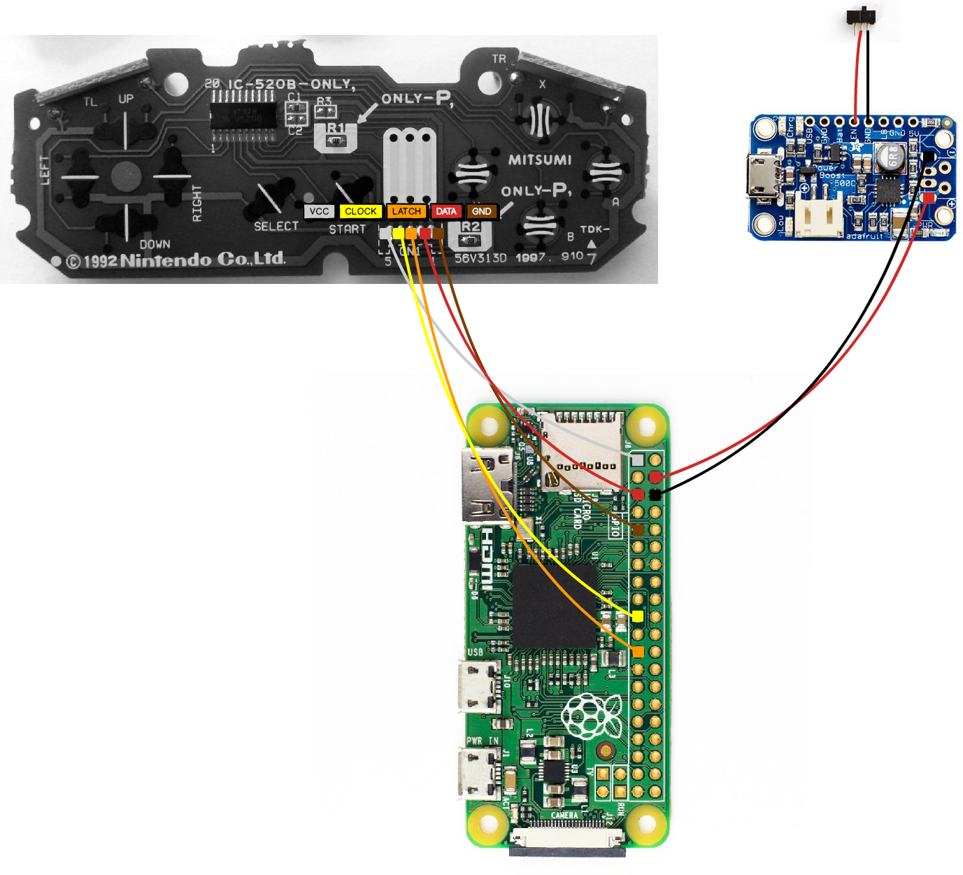
Nothing fires up that childhood nostalgia for me quite like the SNES. Some of my favorite childhood memories are of exploring the hidden worlds in Super Mario World, thrashing sewer baddies in Teenage Mutant Ninja Turtles, and catching on fire in NBA Jam.

To recapture some of that magic, I hacked a Raspberry Pi powered emulation device inside of an SNES controller. Running off a Li-Po battery, the controller connects to the TV via an HDMI cable and allows the player to chose from a variety of NES, SNES, and Genesis games. An RGB LED connected to the charging circuit provides status indication for the device: on (blue), low battery (red), charing (yellow), charged (green). The device is named Z(ero) SNES as a nod to the first SNES emulator I ever used, dos-based ZSNES.

Project Goal/Constraints:

  • Build all-in-one emulation device into OEM SNES controller. Device should be self-contained and aesthetically pleasing--smooth(ish) cuts, polished finishes. Device should provide status indication via LED.

Materials Used

  • Official SNES controller
  • Raspberry Pi Zero
  • 16GB MicroSD card
  • Adafruit Power Boost 500c
  • 500mAh Li-Po battery
  • Mini HDMI to HDMI adapter
  • On/off switch
  • RGB LED

Hardware

IMG_1421

Controller Breakdown

IMG_1369

The first and easiest step is breaking the SNES controller. There are five phillips head screws on the back that can easily be removed with a jewler's screwdriver or PC screwdriver.

Next, remove the SNES cable by de-soldering the pin headers from the front section of the board. I highly recommend an all-in-one iron + desoldering pump for this, since heating the pads with an iron and using desoldering braid is a bit of a pain.

IMG_1370

IMG_1371

At this point, we are ready to replace the pins with wires that will connect to the GPIO ports of the Pi. I purposely used the same color wires as the OEM harness to avoid future confusion.

NOTE: the photo below shows the wires soldered into the PCB from front to back. After making a second one of these, I would recommend going back to front to make everything fit into the case better.

IMG_1422

Raspberry Pi

rpi_zero_pinout

I used this handy graphic put together by Anthony Caccese to wire up the Pi itself. Basically, we're hooking the SNES controller up to 3.3v power (white), GPIO3 (red), GPIO17 data (brown), GPIO10 (yellow), and GPIO11 (orange).

The additional red and black wires are the 5v / ground for the charging circuit.

IMG_1423

IMG_1424

led_test2

resistor wiring

fitting

SNES_overhead

yellow_side

Software

One of the most challenging parts of this project turned out to be the initial software configuration. For whatever reason, the version of RetroPie I downloaded from their website and wrote to my SD card had botched kernel headers that would not allow me to install the controller drivers.

In case anyone comes up against that issue in the future, I've created a ready to go image with RetroPie installed and the drivers enabled (current as of 12/2016). There are no ROMs included in the image, you will need to add them over SSH/WiFi.

Backend Setup (via headless SSH)

One of the greatest things I learned while working on this project was that the Pi Zero will allow headless SSH pretty much out of the box. This means that you can use a single USB cable to power/connect to the Pi and modify config files after making a small change to two boot files. See the steps here, big thanks to Andrew Mulholland for his work on this.

After following the steps outlined on Andrew's blog, connect the pi to your computer via the micro USB port labeled USB (not "PWR IN"). Fire up your favorite SSH program (Putty on Windows, terminal on Linux/OSX) and you should be able to connect to the Pi as "pi@retropie.local" password: "raspberry".

Now you can enable the drivers for the controller by running the RetroPi startup script in /xxx/xxx/ :

./path/to/script

Follow menu options 01 xxx > 05 xxx > blah blah

Finally, you will need to update the gamecon driver configuration file in /etc/modprobe.d :

sudo nano /etc/modeprobe.d/gamecon.conf // change line to read "options gamecon_gpio_rpi map=0,0,0,0,0,1"

Press ctrl + x to save and exit.

At this point, you can transfer ROMs to the /xxx/rom/ directory. I personally prefer to use a GUI for doing this, such as WinSCP (Windows) or Cyberduck (OSX).

If you are interested in running updates or installing additional packages, you will need to configure the pi to connect over Ethernet/WiFi and plug in an adapter. You can do this by editing the WPA Supplicant configuration file found at /etc/network/wpa_supplicant.conf

sudo nano /etc/network/wpa_supplicant.conf

Add your wireless network info into a new line of the config file in the following form (replacing network_name and pasword), press ctrl + x to save and exit:

network={ ssid="network_name" psk="password" }

Frontend Setup

Plug in your finished product to the TV and boot it up! It will take 30 seconds to a minute to load into EmulationStation.

Use your keyboard to navigate to the input config menu by pressing Enter > Configure Inputs. Follow the directions to configure the SNES controller buttons.


SmartStarter, part 1

car_starter_square This is part 1 of a 3 part series on the SmartStarter project.

  • Part 1 covers hardware, setup, and software development of the Arduino + GSM functionality.
  • Part 2 covers hardware and software revisions and integration of the unit into the car
  • Part 3 covers setup and development of the GPS tracking functionality.

Recently, I've been toying around with the idea of building more complicated IoT devices. Inspired by recent visits to HackManhattan and FatCat Fab Lab, I decided to pull the trigger on an Adafruit GSM shield. Around the same time, I was looking for a way to expand the range of the remote starter in my car--I often end up parked 3-4 blocks away from my apartment, which renders the remote starter in my car useless. Nothing like walking to your car in 20 degree weather and spending another ten minutes in the car freezing your ass off becuase the range on your remote starter is garbage.

And so, out of these two things, the SmartStarter project was born. By combining an Arduino, GSM shield, and a spare car remote, I can now remotely start and lock/unlock my car anywhere I have cell service.

At a later date, I plan to capture GPS coordinates via the onboard GPS chip at 30 minute intervals and push them to a MySQL database on my AWS server.


Full breakdown and code below the break.

Project Goals:

  1. Remotely start or lock/unlock car via text (part 1)
  2. Power device via car always on 12V rail (part 2)
  3. Obtain GPS signal via OEM antenna and push coordinates into database at 30 min intervals (part 3)
  4. Write front end Google Maps overlay for GPS coordinates (part 3)

Materials Used

  • Arduino Uno
  • Adafruit FONA 3g GSM shield w/ 3g SIM
  • GSM antenna
  • GPS antenna -- I am splicing into the factory SiriusXM antenna in my car
  • Li-Po battery
  • Spare car remote

Hardware

Any microprocessor programmable via the Arduino IDE will work, in this case I went with an official Arduino Uno. When looking at GSM shields, I was only interested in shields with 3g compatible chipsets. I take my car out to some remote areas when I go climbing and backpacking, so I wanted to guarantee the most amount of coverage possible. I also had some concern with sunsetting 2g coverage rendering my device useless in the near future.

I chose the Adafruit 3g FONA Shield for a few reasons: it's cost effective, it has an onboard GPS chip, the FONA library is well supported in the maker scene, and Adafruit is an awesome NYC based company.

Setup

Arduino + FONA + Antennas + Battery

adafruit_fona

One of the awesome things about Adafruit is that they provide in-depth setup documentation for most of their products. In this case, they have a overview that walks you through basic setup of the FONA 3g GSM shield. For the purposes of this blog post, I'm going to skip those steps, since Adafruit already covers them so well.

Car Remote

I disassembled the car remote to take a look at the buttons used for each item: lock, unlock, and remote start.

[IMG]

I then used a multimeter in continuity setting to get an understanding of how the press button switches worked. I learned that the buttons had two negative (ground) and two positive leads, connected to a 3v coin battery on the other side.  I realized that I could ground the negative side of the switches and use the Arduino to switch between I/O pin mode to effectively tri-state the switches, in order to get an electronic button press.

I soldered connections to each of the necessary pads:

img_1339_text

I then connected the positive leads to the Arduino IO pins and the negative leads to ground on the breadboard:

img_1341_text

Button Press Test

To test my connections, I wrote a basic Arduino program that sent a low signal to pin 5 in output mode, waited a second, and changed the pin to input mode--"pressing" the lock button on the remote.

void setup() {
   pinMode(5, OUTPUT);
}

void loop() {

  int lock(){
    digitalWrite(5, LOW);
    delay(1000);
    pinMode(5, INPUT);
  }  

}

Hooray, it works!

[GIF]


Code

At this point, I was ready to write an Arduino sketch. I needed code that would check the SIM card for an SMS, parse the SMS text, and run a specific function based on the SMS text.

Fortunately, Adafruit had a project guide for an SMS controlled door lock that I was able to use as the basis for my SMS read-in code. It already had the bones for the SMS read-in functionality, I just needed to build my specific functionality on top.

Note: all credit for the open-sesame code goes to LadyAda of Adafruit; her full code for that project is on the Adafruit Github page.

My Code

Using the open-sesame code as a base, I wrote a series of functions (doors, remote, and sms) that interact with the key-fob pins depending on the text of the SMS message. After attempting to lock/unlock or remote start the car, the device will send a response SMS back to the sender, indicating that it has attempted to "press" that button.

Success!

[GIF]

Full code on Github [fac_icon icon="github"]

#include 
#include "Adafruit_FONA.h"

#define FONA_RX 2
#define FONA_TX 3
#define FONA_RST 4
#define FONA_RI 5

#define LOCK_PIN 6
#define UNLOCK_PIN 7
#define REMOTE_PIN 8

#define LED 13

#define LOCK true
#define UNLOCK false

#define BUSYWAIT 5000  // milliseconds

// stores senderient SMS #
char sender[25];

// this is a large buffer for replies
char replybuffer[255];

SoftwareSerial fonaSS = SoftwareSerial(FONA_TX, FONA_RX);

Adafruit_FONA_3G fona = Adafruit_FONA_3G(FONA_RST);

uint8_t readline(char *buff, uint8_t maxbuff, uint16_t timeout = 0);

boolean fonainit(void) {
  while (!Serial);

  fonaSS.begin(4800);
  Serial.println(F("Initializing....(May take 3 seconds)"));

  if (! fona.begin(fonaSS)) {
    Serial.println(F("Couldn't find FONA"));
    return false;
  }
  Serial.println(F("FONA is OK"));
  return true;

}

void setup() {

  // set LED output for debugging
  pinMode(LED, OUTPUT);

  // set key fob pins so they are off
  pinMode(LOCK_PIN, INPUT);
  pinMode(UNLOCK_PIN, INPUT);  
  pinMode(REMOTE_PIN, INPUT);

  Serial.begin(115200);
  Serial.println(F("FONA basic test"));

  while (! fonainit()) {
    delay(5000);
  }

  // Print SIM card IMEI number.
  char imei[15] = {0}; // MUST use a 16 character buffer for IMEI!
  uint8_t imeiLen = fona.getIMEI(imei);
  if (imeiLen > 0) {
    Serial.print("SIM card IMEI: "); Serial.println(imei);
  }

  pinMode(FONA_RI, INPUT);
  digitalWrite(FONA_RI, HIGH); // turn on pullup on RI
  // turn on RI pin change on incoming SMS!
  fona.sendCheckReply(F("AT+CFGRI=1"), F("OK"));
}

int8_t lastsmsnum = 0;

void loop() {
   digitalWrite(LED, HIGH);
   delay(100);
   digitalWrite(LED, LOW);

  while (fona.getNetworkStatus() != 1) {
    Serial.println("Waiting for cell connection");
    delay(6000);
  }

  // Check if the interrupt pin went low, 
  // and after BUSYWAIT milliseconds break out to check
  // manually for SMS' and connection status
  for (uint16_t i=0; i<BUSYWAIT; i++) {
     if (! digitalRead(FONA_RI)) {
        // RI pin went low, SMS received?
        Serial.println(F("RI went low"));
        break;
     } 
     delay(1);
  }

  int8_t smsnum = fona.getNumSMS();
  if (smsnum < 0) {
    Serial.println(F("Could not read # SMS"));
    return;
  } else {
    Serial.print(smsnum); Serial.println(F(" SMS on SIM card!"));
  }

  if (smsnum == 0) return;

  // there's an SMS!
  uint8_t n = 0; 
  while (true) {
     uint16_t smslen;
     //char sender[25];

     uint8_t len = fona.readSMS(n, replybuffer, 250, &smslen); // pass in buffer and max len!
     // if the length is zero, its a special case where the index number is higher
     // so increase the max we'll look at!
     if (len == 0) {
        Serial.println(F("[empty slot]"));
        n++;
        continue;
     }
     if (! fona.getSMSSender(n, sender, sizeof(sender))) {
       // failed to get the sender?
       sender[0] = 0;
     }

     Serial.print(F("***** SMS #")); Serial.print(n);
     Serial.print(" ("); Serial.print(len); Serial.println(F(") bytes *****"));
     Serial.println(replybuffer);
     Serial.print(F("From: ")); Serial.println(sender);
     Serial.println(F("*****"));

     if (strcasecmp(replybuffer, "lock") == 0) {
       // lock the doors
       digitalWrite(LED, HIGH);
       doors(LOCK);
       digitalWrite(LED, LOW);
     }
     if (strcasecmp(replybuffer, "unlock") == 0) {
       // unlock the doors
       digitalWrite(LED, HIGH);
       doors(UNLOCK);
       digitalWrite(LED, LOW);
     }
     if (strcasecmp(replybuffer, "remote") == 0) {
       // start/stop the car
       digitalWrite(LED, HIGH);
       remote();
       digitalWrite(LED, LOW);
     }

     delay(3000);
     break;
  }  
  fona.deleteSMS(n);

  delay(1000); 
}

void doors(boolean locked){
  if (locked) {
    pinMode(LOCK_PIN, OUTPUT);
    digitalWrite(LOCK_PIN, LOW);
    delay(1000);
    pinMode(LOCK_PIN, INPUT);

    Serial.println("Attemped to lock doors");
    Serial.print("Attempting to send SMS to: "); Serial.println(sender);
    sms(sender, "Door lock signal sent!");
  } else {
    pinMode(UNLOCK_PIN, OUTPUT);
    digitalWrite(UNLOCK_PIN, LOW);
    delay(1000);
    pinMode(UNLOCK_PIN, INPUT);

    Serial.println("Attemped to unlock doors");
    Serial.print("Attempting to send SMS to: "); Serial.println(sender);
    sms(sender, "Door unlock signal sent!");
  }
}

void remote(){
  pinMode(REMOTE_PIN, OUTPUT);
  digitalWrite(REMOTE_PIN, LOW);
  delay(1000);
  pinMode(REMOTE_PIN, INPUT);

  Serial.println("Attemped to remote start/stop car");
  Serial.print("Attempting to send SMS to: "); Serial.println(sender);
  sms(sender, "Remote start/stop signal sent!");
}

void sms(char* sender, char* message){
  flushSerial();
  if (!fona.sendSMS(sender, message)) {
    Serial.println(F("Failed"));
  } else {
    Serial.print(F("Sent SMS response to: ")); Serial.println(sender);
  }
}

void flushSerial() {
  while (Serial.available())
    Serial.read();
}

NYC Subway Status Touchscreen

img_1202 If you rely on public transportation for your daily commute, you know how frustrating it can be to miss a train. Worse still, if the trains happen to be delayed (or running express past your stop), you may end up walking 20+ minutes to a different stop/line.

This is often the case for me in Brooklyn, where the J and M lines run express past my stop for seemingly no reason. After getting fed up with walking 2 extra stops to catch an express train for the millionth time, I decided to do something about it. I could check Google Maps transit layer on my phone every day, but I honestly never think to pull it up. Instead, I decided to

It turns out that the New York MTA hosts the service status of all train lines and buses in a publicly accessible XML text file on their website. With a little bit of Python scripting, I was able to scrape, clean, and store the subway data. I pushed this data into a Python GUI that allows the user to see the status of each line, and click on the status message to get more details. I loaded the program onto a Raspberry Pi connected to a 7" touchscreen and mounted it by my front door.

See the GUI in action here:

python_gui

Full breakdown and code below the break.

Materials Used

  • Raspberry Pi 2
  • SDHC card with Raspbian
  • Belkin Wifi Adapter (not needed if using Pi 3)
  • Official Raspberry Pi 7" Touchscreen
  • Python 3.5

Hardware

Raspberry Pi 2

I happened to have an old Pi 2 laying around from an XBMC media center build I stopped using a couple years ago. I formatted the SD card with a fresh copy of Raspian and added a wifi adapater to connect Pi to my home wLAN.

Official Raspberry Pi Screen

My goal was to keep this build as simple as possible, so I went with the official Pi 7" touchscreen as the display for this project.

img_1157

The screen itself it pretty much plug and play: display goes via DPI port to the pi, 2 pins to the pi, and 2 pins to the GPIO.

7intscontents

img_1159

5 minutes later and voila, touchscreen pi!

img_1160

At this point, the hardware is good to go. Time to write some code.

Code

Scraping the MTA Data

I decided to use Python for this project because it comes preinstalled on the Pi, has support for the Pi's GPIO pins, and has great web scraping libraries. I personally prefer and use Python 3.x over 2.x, but the same could be accomplished in 2.x with a bit of tweaking.

Below is the code for the basic scraping and parsing functionality:

from bs4 import BeautifulSoup
from urllib.request import urlopen
from collections import OrderedDict

url = 'http://web.mta.info/status/serviceStatus.txt'
xml = urlopen(url).read()
soup = BeautifulSoup(xml, "xml")

timestamp = soup.timestamp.text
subway = soup.subway

status_dict = {}

all_lines = subway.findAll('line')
for line in all_lines:
    line.find('line')
    for info in line:
        name = line.find('name').text
        status = line.find('status').text
        text = line.find('text').text
        text = text.replace('<','<').replace('>','>').replace(' ',' ')

        if line.find('Date').text == '': 
            datetime = timestamp
        else:
            datetime = line.find('Date').text.strip(' ') + ' ' + line.find('Time').text.strip(' ')
        status_line = [status, datetime, text]
    status_dict[name] = status_line

sorted = OrderedDict(sorted(status_dict.items()))
print(sorted)

In the code above, we start by importing the relevant libraries: BeautifulSoup, URLOpen, and OrderedDict.

from bs4 import BeautifulSoup
from urllib.request import urlopen
from collections import OrderedDict

Next, we setup BeautifulSoup to read in the XML file by providing the URL for the file, opening it, and parsing it with the XML library.

url = 'http://web.mta.info/status/serviceStatus.txt'
xml = urlopen(url).read()
soup = BeautifulSoup(xml, "xml")

At this point, we only care about two XML tags: timestamp and subway. We don't want bus times, and we will need the timestamp tag later. We should also create a dictionary to store all of the data.

timestamp = soup.timestamp.text
subway = soup.subway

status_dict = {}

Within the subway tag, there exists individual lines, which contain tags for the line name, line status, and description of that status. We can write a simple nested loop that pulls out each line from subway, and all 3 tags from each line.

all_lines = subway.findAll('line')
for line in all_lines:
    line.find('line')
    for info in line:
        name = line.find('name').text
        status = line.find('status').text
        text = line.find('text').text

At this point, we have the data we want and can do some basic cleanup on it. For whatever reason, the MTA doesn't update the individual line time stamp for lines where service status == "GOOD SERVICE". In order to provide a complete data, we need to use the time stamp we got earlier from the parent XML file. This is slightly complicated by the fact that the time stamp in the XML file is in a different format from the time stamp provided by the line status. So, we need to first check if the line time stamp exists, use the parent time stamp if not, or use the line time stamp and reformat it.

        text = text.replace('<','<').replace('>','>').replace(' ',' ')

        if line.find('Date').text == '': 
            datetime = timestamp
        else:
            datetime = line.find('Date').text.strip(' ') + ' ' + line.find('Time').text.strip(' ')

Finally, we take each of these tags and stick them into a list item. This list item goes into a dictionary, which gets sorted and put into an ordered dictionary. This way, the lines will always be returned in the same order. This example then goes on print the dictionary; see the full code below to see how this is integrated into the GUI.

        status_line = [status, datetime, text]
    status_dict[name] = status_line

sorted = OrderedDict(sorted(status_dict.items()))
print(sorted)


Python GUI

I used Python library Tkinter to build the GUI for this project, which was probably the hardest part of the whole thing. I had 0 experience with Tkinter (or UI design in general) when I started. That said, I think it turned out well.

Full code available on GitHub [fac_icon icon="github"]

###   Created by Nick Wallace  ###
###                            ###
###                            ###

import re
from tkinter import *
from tkinter import font
from bs4 import BeautifulSoup
from urllib.request import urlopen
from PIL import ImageTk, Image
from collections import OrderedDict

root = Tk()
root.title("MTA Service Status")
root.configure(background = "white")
#root.geometry('800x480')
#root.attributes('-fullscreen', True)

root.columnconfigure(0, weight = 1)
root.columnconfigure(1, weight = 1)
root.columnconfigure(2, weight = 1)
root.columnconfigure(3, weight = 1)

header_font = font.Font(family='Heveltica', weight = 'bold', size=13)
main_font = font.Font(family = 'Heveltica', size = 12)

def getData():
    global sort

    url = 'http://web.mta.info/status/serviceStatus.txt'
    xml = urlopen(url).read()
    soup = BeautifulSoup(xml, "xml")
    timestamp = soup.timestamp.text
    subway = soup.subway
    status_dict = {}
    all_lines = subway.findAll('line')
    for line in all_lines:
        line.find('line')
        for info in line: 
            name = line.find('name').text
            status = line.find('status').text
            text = line.find('text').text
            text = text.replace('<','<').replace('>','>').replace(' ',' ')

            if line.find('Date').text == '': 
                datetime = re.sub(':[:]*.{2}[:]* {1}', '', timestamp)
            else:
                datetime = line.find('Date').text.strip(' ') + ' ' + line.find('Time').text.strip(' ')
            status_line = [status, datetime, text]
        status_dict[name] = status_line
    sort = OrderedDict(sorted(status_dict.items()))
    return sort

def firstRun(dict):
    global labels
    labels = {}

    header_img = Label(root, text = 'LINE', font = header_font, bg = 'white')
    header_img.grid(columnspan = 2)

    header_name = Label(root, text = 'STATUS', anchor = 'center', font = header_font, bg = 'white')
    header_name.grid(row = 0, column = 2)

    header_timestamp = Label(root, text = 'TIME', anchor = 'center', font = header_font, bg = 'white')
    header_timestamp.grid(row = 0, column = 3)

    rc = 1

    for k, v in dict.items():
        img_url = 'c://Temp/imgs/' + k + '.png'
        img = ImageTk.PhotoImage(Image.open(img_url))

        Grid.rowconfigure(root, rc, weight=1)
        Grid.columnconfigure(root, rc, weight=1)

        line_img = Label(root, image = img, bg = 'white')
        line_img.image = img
        line_img.grid(row = rc, columnspan = 2)

        #line_name = Label(root, text = k, bg = 'white')
        #line_name.grid(row = rc, column = 1, sticky = W)
        labels[(rc, 1)] = k

        line_status = Label(root, text = ' ' + v[0], font = main_font, bg = 'green' if v[0] == 'GOOD SERVICE' else 'yellow' if v[0] == 'PLANNED WORK' else 'red')
        line_status.grid(row = rc, column = 2)
        if v[0] not in ['GOOD SERVICE']: line_status.bind('', addMessage)
        labels[(rc, 2)] = line_status

        line_timestamp = Label(root, text = ' ' + v[1], font = main_font, bg = 'white')
        line_timestamp.grid(row = rc, column = 3)
        labels[(rc, 3)] = line_timestamp

        rc += 1

    blank_line = Label(root, text = '', bg = 'white')
    blank_line.grid(row = rc)

def addMessage(event): 
    global msg_label

    grid_info = event.widget.grid_info()
    line = labels[(grid_info['row'],1)]

    msg_text = re.sub('<[^>]*>', '', sort[line][2])
    msg_text = re.sub('&[^;]*;', ' ', msg_text)
    msg_text = re.sub('\n+', '\n', msg_text)
    msg_text = re.sub(' +', ' ', msg_text)
    msg_text = re.sub('Show.*?Note:', '', msg_text)
    msg_text = re.sub('Key.*?Note:', '', msg_text)
    msg_text = re.sub(r' [ad].*relay.', '', msg_text)

    msg_label = Label(root, text = msg_text, anchor = 'w', justify = 'center', wraplength=480)
    msg_label.grid(row = grid_info['row'] + 1, columnspan = 4)
    msg_label.bind('', removeMessage)

def removeMessage(event):
    msg_label.grid_forget()   

def refresh(dict):
    rc = 1

    for k, v in dict.items():
        labels[(rc,2)].config(text = ' ' + v[0], bg = 'green' if v[0] == 'GOOD SERVICE' else 'yellow' if v[0] == 'PLANNED WORK' else 'red')
        labels[(rc,3)].config(text = ' ' + v[1])

        rc += 1

def exit():
    root.quit()

firstRun(getData())

refreshButton = Button(root, text = "Refresh", command =lambda: refresh(getData()), height = 1, width = 15).grid(row = 15, column = 0, columnspan = 3) 
exitButton = Button(root, text = "Exit", command = exit, height = 1, width = 15).grid(row = 15, column = 2, columnspan = 3)
blank_line = Label(root, text = '', bg = 'white')
blank_line.grid(row = 16)

mainloop()


GUI in Action

The GUI is still a WIP, but click below to see the basic functionality: python_gui