 Nothing fires up that childhood nostalgia for me quite like the SNES. Some of my favorite childhood memories are of exploring the hidden worlds in Super Mario World, thrashing sewer baddies in Teenage Mutant Ninja Turtles, and catching on fire in NBA Jam.
To recapture some of that magic, I hacked a Raspberry Pi powered emulation device inside of an SNES controller. Running off a Li-Po battery, the controller connects to the TV via an HDMI cable and allows the player to chose from a variety of NES, SNES, and Genesis games. An RGB LED connected to the charging circuit provides status indication for the device: on (blue), low battery (red), charing (yellow), charged (green). The device is named Z(ero) SNES as a nod to the first SNES emulator I ever used, dos-based ZSNES.
Project Goal/Constraints:
- Build all-in-one emulation device into OEM SNES controller. Device should be self-contained and aesthetically pleasing--smooth(ish) cuts, polished finishes. Device should provide status indication via LED.
Materials Used
- Official SNES controller
- Raspberry Pi Zero
- 16GB MicroSD card
- Adafruit Power Boost 500c
- 500mAh Li-Po battery
- Mini HDMI to HDMI adapter
- On/off switch
- RGB LED
Hardware

Controller Breakdown

The first and easiest step is breaking the SNES controller. There are five phillips head screws on the back that can easily be removed with a jewler's screwdriver or PC screwdriver.
Next, remove the SNES cable by de-soldering the pin headers from the front section of the board. I highly recommend an all-in-one iron + desoldering pump for this, since heating the pads with an iron and using desoldering braid is a bit of a pain.


At this point, we are ready to replace the pins with wires that will connect to the GPIO ports of the Pi. I purposely used the same color wires as the OEM harness to avoid future confusion.
NOTE: the photo below shows the wires soldered into the PCB from front to back. After making a second one of these, I would recommend going back to front to make everything fit into the case better.

Raspberry Pi

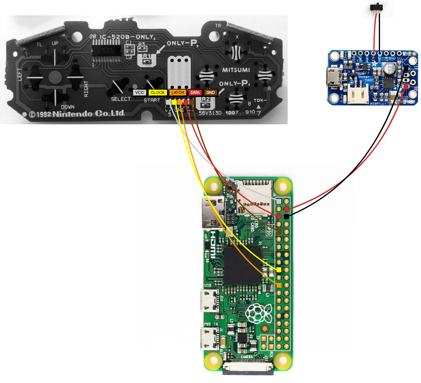
I used this handy graphic put together by Anthony Caccese to wire up the Pi itself. Basically, we're hooking the SNES controller up to 3.3v power (white), GPIO3 (red), GPIO17 data (brown), GPIO10 (yellow), and GPIO11 (orange).
The additional red and black wires are the 5v / ground for the charging circuit.


Software
One of the most challenging parts of this project turned out to be the initial software configuration. For whatever reason, the version of RetroPie I downloaded from their website and wrote to my SD card had botched kernel headers that would not allow me to install the controller drivers.
In case anyone comes up against that issue in the future, I've created a ready to go image with RetroPie installed and the drivers enabled (current as of 12/2016). There are no ROMs included in the image, you will need to add them over SSH/WiFi.
Backend Setup (via headless SSH)
One of the greatest things I learned while working on this project was that the Pi Zero will allow headless SSH pretty much out of the box. This means that you can use a single USB cable to power/connect to the Pi and modify config files after making a small change to two boot files. See the steps here, big thanks to Andrew Mulholland for his work on this.
After following the steps outlined on Andrew's blog, connect the pi to your computer via the micro USB port labeled USB (not "PWR IN"). Fire up your favorite SSH program (Putty on Windows, terminal on Linux/OSX) and you should be able to connect to the Pi as "pi@retropie.local" password: "raspberry".
Now you can enable the drivers for the controller by running the RetroPi startup script in /xxx/xxx/ :
./path/to/script
Follow menu options 01 xxx > 05 xxx > blah blah
Finally, you will need to update the gamecon driver configuration file in /etc/modprobe.d :
sudo nano /etc/modeprobe.d/gamecon.conf
// change line to read "options gamecon_gpio_rpi map=0,0,0,0,0,1"
Press ctrl + x to save and exit.
At this point, you can transfer ROMs to the /xxx/rom/ directory. I personally prefer to use a GUI for doing this, such as WinSCP (Windows) or Cyberduck (OSX).
If you are interested in running updates or installing additional packages, you will need to configure the pi to connect over Ethernet/WiFi and plug in an adapter. You can do this by editing the WPA Supplicant configuration file found at /etc/network/wpa_supplicant.conf
sudo nano /etc/network/wpa_supplicant.conf
Add your wireless network info into a new line of the config file in the following form (replacing network_name and pasword), press ctrl + x to save and exit:
network={
ssid="network_name"
psk="password"
}
Frontend Setup
Plug in your finished product to the TV and boot it up! It will take 30 seconds to a minute to load into EmulationStation.
Use your keyboard to navigate to the input config menu by pressing Enter > Configure Inputs. Follow the directions to configure the SNES controller buttons.